Tutorial 1: Visualizing the Robot
A robot is made of joints connected by links. To promote modularity and reusability, the kinematic and dynamic parameters of a robot are described in a Unified Robot Description Format (URDF) file. A URDF is an XML file built around two core tags: <link> and <joint>.
What is a URDF?
Links
A <link> represents a rigid body in the robot. Each link supports up to three subtags:
| Subtag | Description |
|---|---|
<visual> | Defines the 3D mesh used for rendering in RViz. |
<collision> | Defines the simplified geometry used for collision detection. |
<inertial> | Specifies the mass and inertia tensor used in physics simulation. |
<link name="manipulator_link1">
  <visual>
    <origin xyz="0. 0. 0."/>
    <geometry>
      <mesh filename="package://ulixarm_description/meshes/visual/link_1.stl"/>
    </geometry>
  </visual>
  <collision>
    <origin xyz="0. 0. 0."/>
    <geometry>
      <mesh filename="package://ulixarm_description/meshes/collision/link_1.stl"/>
    </geometry>
  </collision>
  <inertial>
    <origin xyz="0. 0. 0.037"/>
    <mass value="0.480"/>
    <inertia ixx="0.0001" ixy="0.0" ixz="0.0"
             iyy="0.0001" iyz="0.0" izz="0.002"/>
  </inertial>
</link>
Joints
A <joint> connects two links — a parent and a child — and defines how they move relative to each other. The full kinematic chain of the robot is built by chaining joints from the base link to the end-effector.
| Subtag | Description |
|---|---|
<origin> | Position and orientation of the joint frame relative to the parent link. |
<parent> | The upstream link in the kinematic chain. |
<child> | The downstream link driven by this joint. |
<axis> | The axis of rotation or translation, expressed as a unit vector. |
<limit> | Defines the effort, velocity, and angular range constraints of the joint. |
<joint name="joint1" type="revolute">
  <origin rpy="0. 0. 0." xyz="0. 0. 0.0533"/>
  <parent link="manipulator_base_link"/>
  <child link="manipulator_link1"/>
  <axis xyz="0 0 1"/>
  <limit effort="27.0" lower="-1.570796326795" upper="1.570796326795" velocity="8.0"/>
</joint>
You can browse the full URDF of the UlixArm in the ulixarm_description package.
You may notice .xacro files alongside the URDF. Xacro (XML Macros) is a preprocessor for URDF that introduces support for variables, math expressions, and reusable macros, keeping robot descriptions concise and maintainable. Xacro files are automatically compiled into standard URDF at runtime.
For a step-by-step guide on writing your own URDF from scratch, refer to the official ROS 2 URDF tutorial.
Run the Demo
To get started with the first tutorial, you first have to clone the repository
git clone --recursive https://github.com/itacarobotics/ulixarm_ros2.git
navigate into the repository
cd ulixarm_ros2
ROS2 packages are build with colcon. To build the ROS2 workspace run
colcon build
Remember to source the ROS environment if not already added to the .bashrc. As a reminder this can be done by running source /opt/ros/jazzy/setup.bash
Every ROS2 workspace needs to be sourced whenever you open a new terminal. To source the environment run
source install/setup.bash
Add the ulixarm_ros2 setup script to your shell profile so it loads automatically in every new terminal:
echo "source ~/ulixarm_ros2/install/setup.bash" >> ~/.bashrc
source ~/.bashrc
You must source the ROS and ulixarm_ros2 workspace in every new terminal before running any ROS 2 commands. If you completed the Getting Started guide, this is already handled automatically via your .bashrc.
Finally, you can launch the demo
ros2 launch demos display.launch.py
RViz and the joint_state_publisher_gui will open. If you do not see the robot model, follow the steps below.
Open the RobotModel
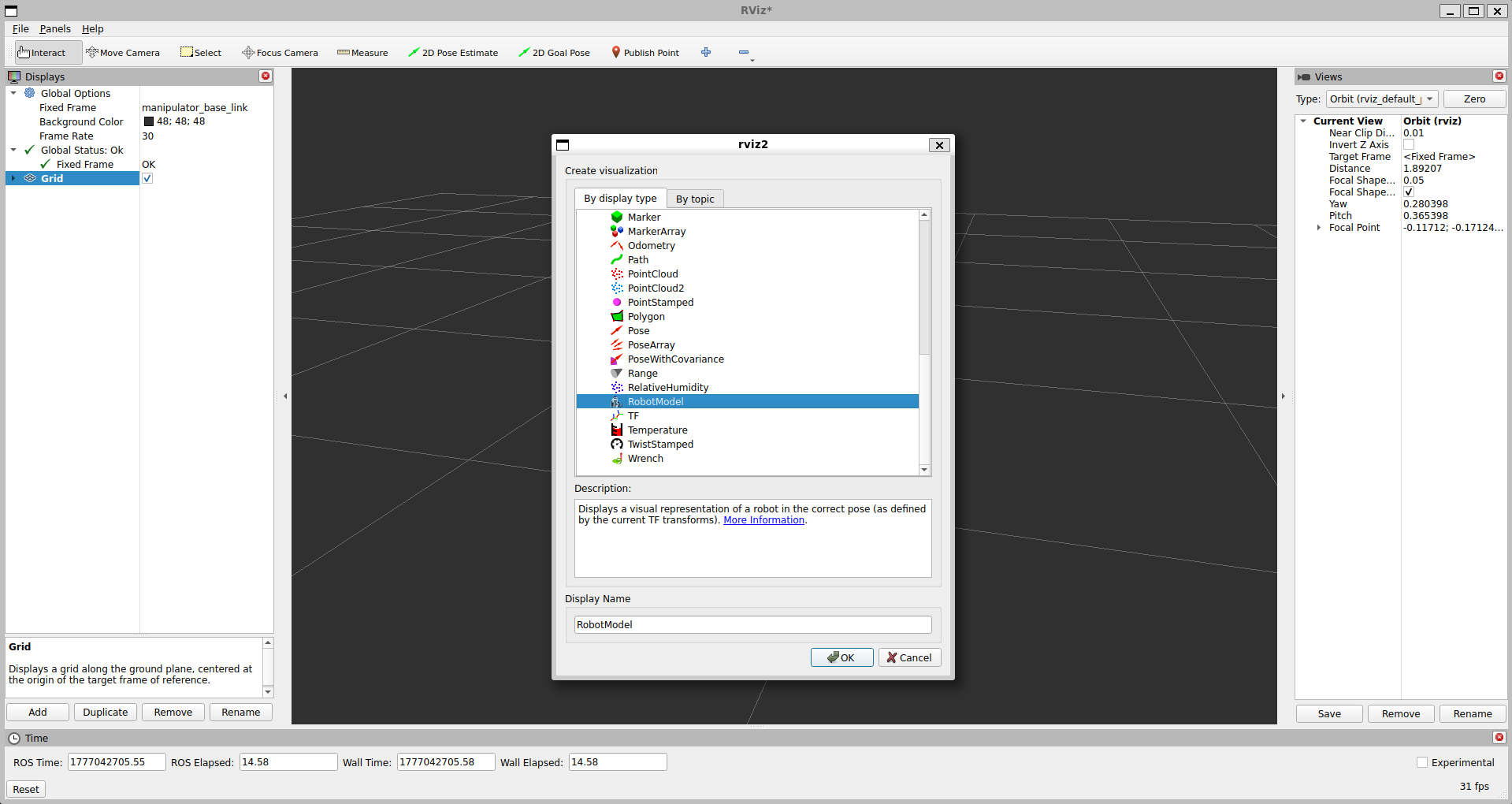
In order for RViz to show the robot model, you have to add the RobotModel.
- Click "Add" in the bottom left corner
- Select the RobotModel
- Click "OK"
Set Description Topic
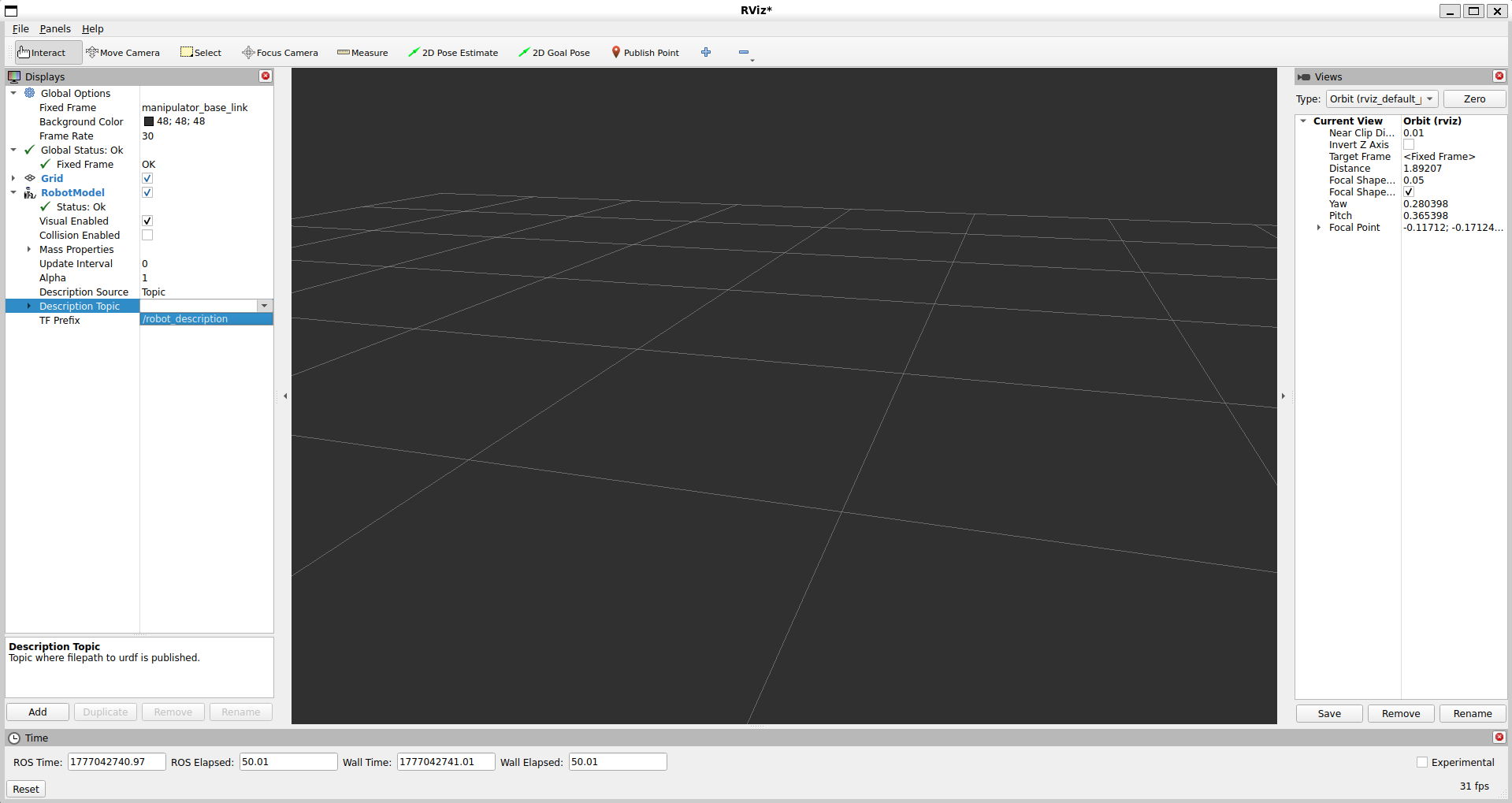
To set the description topic of the robot URDF, click the drop down menu and select /robot_description
Set Fixed Frame
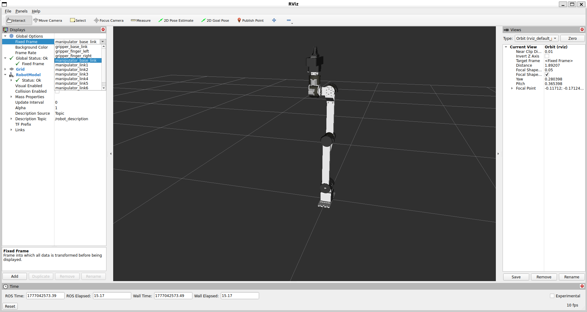
RViz needs to now the fixed frame to get from the URDF. For this select manipulator_base_link
Joint State Publisher GUI
Use the Joint State Publisher GUI to interactively adjust the angle of each joint and observe how the robot moves.
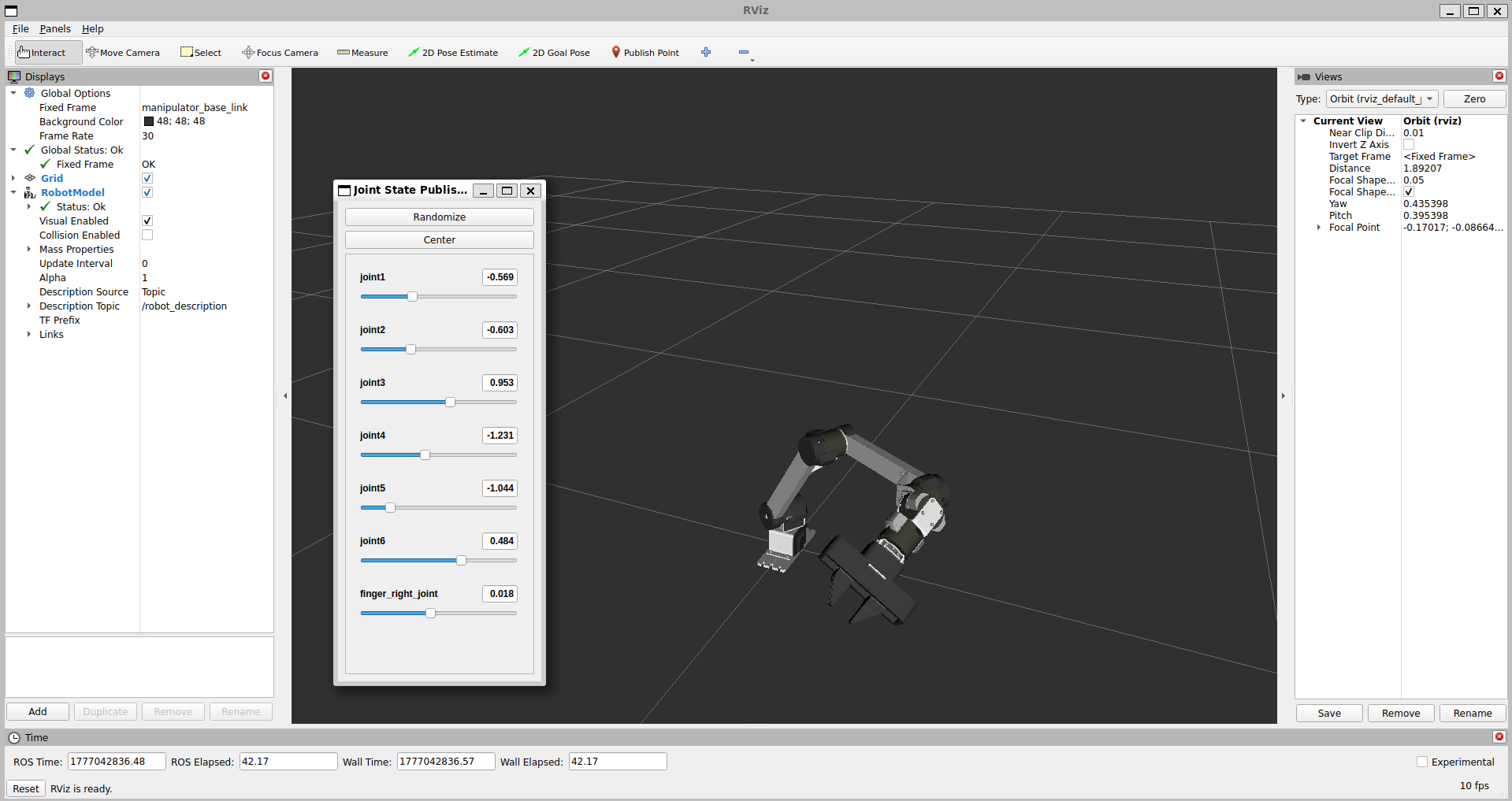
Some joints will rotate clockwise and others counter-clockwise for a positive angle value. This behavior is determined by the physical orientation of the motors in the mechanical assembly.